
- All
- Product Name
- Product Keyword
- Product Model
- Product Summary
- Product Description
- Multi Field Search
 English
Views: 0 Author: Site Editor Publish Time: 2026-10-21 Origin: Site


Static electricity buildup during flammable liquid operations presents a massive hidden danger. Igniting trapped vapors takes only a single spark. This spark can easily occur if your equipment lacks a proper discharge path. Relying on visual inspections alone leaves facilities highly vulnerable to catastrophic explosions.
Routine electrical testing provides the only reliable proof your static dissipation mechanisms work. Internal ground wires and conductive tubes degrade out of sight. They suffer damage from constant flexing, crushing, and daily wear. You cannot see a broken internal wire. You must measure it.
We will walk through the exact steps to verify hose integrity safely. You will learn how to set up a standard digital multimeter. We will explain how to interpret resistance readings accurately. Finally, you will understand how to determine exactly when an assembly must be retired to protect your team.
Electrical continuity tests verify that a fuel transfer hose can safely dissipate static charge from end to end.
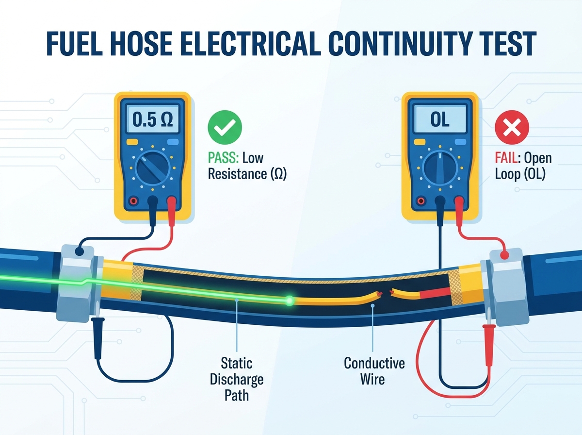
Testing requires a standard digital multimeter set to measure resistance (Ohms), with probes touching the metal couplings on both ends.
A healthy hose typically registers near-zero resistance (often under 10 to 50 ohms, depending on length and manufacturer specifications).
A failed test (showing high resistance or "OL") indicates a broken grounding wire or degraded conductive layer, requiring immediate replacement with a certified antistatic oil transfer hose.
Operations transferring flammable liquids face constant static discharge risks. Rapidly moving fluids generate static electricity through friction. If this charge accumulates, it seeks the fastest path to the earth. An ungrounded system acts like a giant capacitor. It stores energy until a spark arcs across a gap, igniting ambient fumes. This operational hazard leads to facility fires and severe equipment damage. It also triggers massive OSHA and NFPA compliance violations.
Understanding the mechanism of action clarifies why testing matters. Fuel friction strips electrons from the liquid molecules. The host equipment absorbs this electrical charge. Manufacturers build specific dissipation mechanisms into their products to manage this energy. They integrate helical steel wires into the rubber carcass. Alternatively, they use highly specialized conductive rubber compounds. These mechanisms bridge the gap between bonded storage tanks and receiving vessels.
Proper fuel hose grounding and bonding provides a safe, seamless escape route. A successful grounding system creates an uninterrupted, low-resistance path. Static electricity safely travels down the assembly and discharges harmlessly into the earth. If the internal wire snaps, you lose this critical path. The charge builds up behind the break. It waits for an opportunity to arc to a nearby grounded object.
Facility managers must view continuity as a core safety metric. Daily operations put tremendous physical stress on these connections. Trucks run over them. Operators drag them across abrasive concrete. These actions weaken internal components long before the outer cover fails. Relying on pressure tests alone ignores electrical integrity completely.
You must prioritize environmental safety before introducing electrical equipment. Even small digital multimeters generate a tiny electrical current. This current can ignite highly concentrated volatile vapors. You must never test while fuel actively flows. Never attempt this procedure while the assembly remains pressurized.
Drain all remaining liquid back into a secure containment vessel. Purge the interior of flammable vapors. Move the equipment to a well-ventilated, designated maintenance area. Clear the workspace of trip hazards and stray metal objects. Treating the preparation phase seriously prevents tragic accidents.
Gather the following required tools before beginning the assessment:
Digital Multimeter (DMM): Select a device capable of measuring low resistance precisely. It needs an Ohms (Ω) setting.
Extension Wire: Find a spool of insulated copper wire or extra-long test leads. You need this to bridge the physical distance between the two ends.
Alligator Clips: Secure attachment ensures a stable reading. Probes slip easily off curved metal fittings.
Wire Brush or Emery Cloth: Surface oxidation ruins electrical contact. You need abrasive tools to clean corrosion off the metal fittings.
Safety Gloves and Glasses: Always wear standard personal protective equipment during maintenance tasks.
Avoid using cheap, uncalibrated multimeters. You need precision for this job. A difference of a few ohms matters significantly when evaluating specific manufacturer standards. Keep your extension wire insulated to prevent accidental grounding against metal floors. Bare wire touching a steel deck creates a false loop, rendering your test useless.
Verifying fuel transfer hose electrical continuity follows a strict, repeatable process. Skipping steps leads to false positives. A false positive keeps a dangerous assembly in active service. Follow this guide systematically to ensure accurate data.
Turn on your digital multimeter. Set the dial to the lowest resistance setting available. This setting usually displays as 200Ω. Some models feature a dedicated continuity mode. This mode emits an audible beep when it detects a closed circuit. However, you still need to read the actual numeric value.
Next, touch the two multimeter probes directly together. Hold them firmly. Look at the digital screen and wait for the numbers to stabilize. You will typically see a baseline reading between 0.1 and 0.3 ohms. This number represents the inherent resistance of your test leads. Record this number. You will subtract this baseline value from your final measurement to find the true resistance.
Poor contact causes most false failure readings. Metal couplings oxidize over time. Dirt, dried product, and paint also accumulate on the surface. These barriers block the small electrical current generated by your multimeter.
Take your wire brush or emery cloth. Vigorously scrub a small section on both metal fittings. Expose the bright, shiny metal underneath the grime. You need direct metal-to-metal contact for the probes. Do not skip this step, even if the fittings look relatively clean to the naked eye.
Attach one multimeter probe to the freshly cleaned metal coupling at the origin end. Use an alligator clip to clamp it securely in place. If the assembly is short, you can simply touch the other probe to the opposite end.
Longer assemblies require your insulated extension wire. Connect one end of the extension wire to your second multimeter probe. Run the extension wire alongside the assembly down to the destination end. Strip a small piece of insulation off the far end of the extension wire. Clamp this exposed copper tightly to the cleaned metal coupling at the destination end. Ensure the extension wire does not touch any external metal structures.
Turn your attention back to the multimeter screen. Hold the connections steady. Wait a few moments for the reading to stabilize fully. Resistance values sometimes jump around initially as the multimeter sends its current through the full length of the system.
Record the exact ohm value displayed. Subtract your initial baseline reading from this final number. You now have the true electrical resistance of the assembly. For an added layer of security, have a colleague gently flex the rubber carcass near the fittings while you watch the screen. Flexing helps expose frayed internal wires that might temporarily touch when lying flat but pull apart under tension.
You must evaluate your recorded data against strict industry standards. A successful test confirms the internal bonding wire remains intact. It verifies the conductive layer functions exactly as designed.
A healthy, wire-reinforced assembly typically registers near-zero resistance. You want to see readings generally under 10 ohms. Some specific EN/ISO or manufacturer standards dictate slightly different thresholds based on length and material. For example, hoses using inherently conductive rubber compounds often show slightly higher resistance than solid steel wires. However, they should still remain well within the manufacturer's specified safe zone.
Consistent, low resistance means the static charge can flow freely. The internal mechanisms can handle the electron buildup generated during high-speed fluid transfer. Always reference your specific product manual to confirm the exact acceptable ohm range.
High resistance indicates a dangerous problem. A reading of "OL" on your multimeter stands for Open Loop. It means infinite resistance. An OL reading confirms a complete severance of the grounding path. The internal helical wire has snapped completely.
Watch out for heavily fluctuating readings. If the numbers jump wildly between 5 ohms and infinite while you flex the rubber, the wire is failing. The metal strands have likely frayed. They temporarily connect and disconnect as the material bends. This frayed condition is just as dangerous as a complete break. A spark could easily jump across the frayed gap inside the rubber wall during operation.
Hose Resistance Diagnostic Chart
Multimeter Reading | Condition Status | Recommended Action |
|---|---|---|
0 to 10 Ohms | Pass - Optimal | Return to service. Log the test date. |
11 to 50 Ohms | Pass - Marginal | Verify manufacturer specs. Monitor closely. |
Fluctuating (e.g., 5Ω to OL) | Fail - Frayed Wire | Remove from service immediately. |
"OL" or Infinite | Fail - Broken Path | Condemn and destroy. Procure replacement. |
Never attempt to repair a broken internal ground wire. You cannot splice a broken helical spring hidden deep inside thick rubber layers. A failed continuity test renders the equipment permanently unsafe for flammable liquid transfer. Cut condemned assemblies in half to prevent them from accidentally re-entering service.
When an asset fails continuity, replacement is mandatory and urgent. You cannot afford downtime, but you also cannot risk an explosion. Procuring a compliant replacement requires evaluating several key technical dimensions.
Start by analyzing the construction type. Understand the difference between products utilizing a helical grounding wire versus those with conductive rubber. Solid wires offer excellent low-resistance paths but can snap under extreme physical crushing. Inherently conductive rubber compounds cannot snap or break like wires. They provide a more resilient static dissipation method, though their base resistance might be slightly higher.
Next, scrutinize compliance and certifications. Look for verifiable industry ratings. Ensure the product meets API standards. Verify compliance with NFPA 77 guidelines for static electricity. If you handle harsh chemicals alongside petroleum, check for EN 12115 certification. Buying uncertified products introduces immense liability into your operations.
Finally, balance durability with flexibility. Operators must maneuver this equipment daily. A rigid, heavily armored product might survive being run over by a truck. However, if operators struggle to bend it to reach a manifold, they will suffer ergonomic injuries. Find a product that balances robust crush-resistance with practical flexibility.
Upgrading to a premium antistatic oil transfer hose minimizes the risk of sudden wire failure. These specialized products offer superior safety margins for high-volume operations.
Use a single failure as a catalyst to audit your remaining fleet. Institute a formal testing schedule. Quarterly inspections catch degradation before it becomes dangerous. Semi-annual testing might suffice for low-use applications. Document every result in a central maintenance log. Finally, build relationships with vendors who provide factory-tested continuity certifications upon delivery. This guarantees your new assets arrive ready and safe for immediate deployment.
Verifying electrical continuity remains a non-negotiable maintenance procedure. This simple test protects your personnel, your facility, and your local environment from devastating fires. You cannot guess whether a grounding path exists. You must prove it using hard data.
Setting up the circuit takes only a few minutes. Ignoring this basic protocol invites catastrophic static ignition during routine transfers. Do not let complacency put your team at risk.
Facility managers should immediately integrate documented continuity checks into standard operating procedures. Train your maintenance staff on proper multimeter usage. Establish zero-tolerance rules for failing equipment. Retire and destroy non-compliant assets today.
A: We recommend conducting visual inspections daily prior to any transfer operation. Perform formal multimeter continuity tests periodically, such as quarterly or semi-annually. You must also test immediately after an assembly is crushed by a vehicle, severely stretched, or subjected to any significant physical trauma.
A: Yes. Structural integrity is completely separate from electrical integrity. The internal helical ground wire can easily snap under tension while the thick rubber carcass remains entirely leak-free. Passing a hydrostatic pressure test does not guarantee safe static dissipation.
A: Conductive hoses actively conduct electricity, maintaining very low resistance to move heavy charges quickly. Antistatic hoses dissipate static buildup much more slowly to prevent sudden sparking. Both designs effectively mitigate static discharge risks, but their usage depends on your specific application and regulatory standards.