
- All
- Product Name
- Product Keyword
- Product Model
- Product Summary
- Product Description
- Multi Field Search
 English
Views: 0 Author: Site Editor Publish Time: 2026-10-17 Origin: Site


Entrapped air presents a hidden but severe threat to high-volume mining operations. It acts as a physical barrier, severely restricting flow capacity, artificially inflating Total Dynamic Head (TDH), and accelerating wear on expensive pumping equipment. In typical undulating mine terrains, routing heavy-duty lines completely flat remains physically impossible. Operators must face the reality that constant elevation changes naturally capture and hold air within the fluid network. Therefore, proactive air management is an absolute necessity rather than a mere operational afterthought.
This article explores the precise mechanics behind air binding and the resulting equipment risks. You will learn how strategic routing, appropriate fluid velocity maintenance, and targeted hardware integration prevent these critical blockages. By applying these engineering principles, you can secure reliable, uninterrupted water transfer across your entire site.
Air Binding Costs: Unmanaged air pockets act as physical restrictions, reducing pipe cross-sections and increasing friction loss, which forces pumps to work outside their Best Efficiency Point (BEP).
Elevation is the Catalyst: The natural buoyancy of air causes it to accumulate at local high points; managing mine dewatering hose elevation changes is the primary preventative step.
Velocity Matters: Maintaining minimum fluid velocities (typically >1.5 m/s) helps sweep entrained air bubbles through the system before they can coalesce into blocking pockets.
Hardware Intervention: Strategic placement of water transfer hose air release valves is non-negotiable for long-distance, high-volume fluid transfer networks.
Entrapped air actively disrupts fluid dynamics across your entire pumping network. We refer to this problematic phenomenon as "air binding." When air pockets in mine dewatering hose lines form, they create a stubborn physical restriction. This blockage artificially chokes the internal diameter of your pipeline. A mere 10% accumulation of air volume can slash overall water flow by up to 30%. This drastic flow reduction forces centrifugal pumps to operate far outside their Best Efficiency Point (BEP). As a result, energy consumption spikes while actual water removal plummets.
Compressed air bubbles behave highly unpredictably under varying pressure states. They violently expand or collapse as they travel through the system. This rapid volumetric change causes intense pressure surges known as water hammer. These mechanical shockwaves carry immense destructive force. They can easily rupture flexible layflat jackets or blow out mechanical couplings.
Furthermore, if air pockets travel backward or get sucked into the pump volute, they trigger severe impeller cavitation. The collapsing bubbles pit the metal surfaces of the impeller. Over time, this erosion destroys the pump internals, leading to catastrophic equipment failure.
You measure operational success through stable, predictable performance metrics. Successful air management eliminates erratic pressure spikes. You should observe highly consistent flow rates at the discharge point. Additionally, operators will notice significantly reduced pump vibration during daily inspections. Finally, proper venting eliminates localized hose bulging, which often indicates trapped pressurized air.
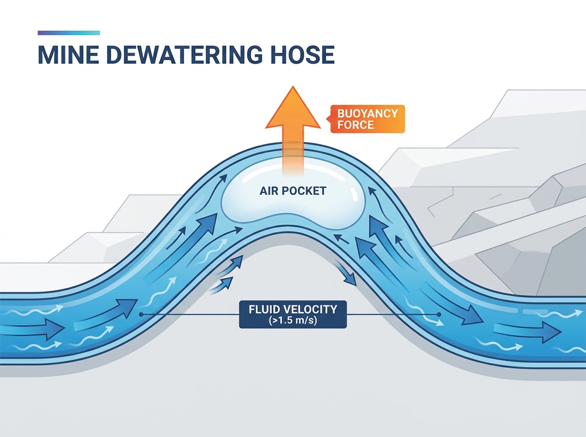
Open-pit and underground mining operations feature notoriously harsh terrains. You must constantly route heavy lines over protective berms, steep highwalls, and access ramps. These necessary physical obstacles create distinct inverted U-shapes along the route. Because air is significantly lighter than water, it naturally travels upward. It permanently traps itself at the crest of these inverted U-shapes. We must carefully manage mine dewatering hose elevation changes to mitigate this natural accumulation.
Basic physics dictates exactly how entrapped air behaves in a fluid stream. The buoyant force constantly pushes gas bubbles upward toward the highest elevation. Conversely, the fluid drag force pushes those same bubbles forward through the line. If the water velocity drops too low, the buoyant force easily overwhelms the drag force.
When this happens, air permanently lodges at the crest of the elevation change. It will not move regardless of how long the pump runs. Engineering standards dictate that you need internal fluid velocities above 1.5 meters per second (m/s). This minimum velocity provides enough drag to sweep entrained air bubbles through the system before they coalesce.
Engineering teams must comprehensively profile the site topography before unrolling a single meter of line. You should utilize GPS or drone survey data to map the intended path.
Identify every major berm crossing.
Mark the peak of any ramp transitions.
Highlight areas where the line traverses over boulders or existing pipe bridges.
By identifying these inevitable local peaks, you pinpoint the exact locations where mechanical intervention will be required. Proactive mapping saves countless hours of troubleshooting later.
Topographical planning alone cannot eliminate every bubble. Hardware intervention remains absolutely essential for long runs. You need precise water transfer hose air release mechanisms to protect the infrastructure. These specialized devices automatically vent accumulated gas without leaking valuable process water.
Industry engineers categorize venting hardware into three distinct classes. You must select the correct class for your specific application stage.
Valve Technology Comparison Chart
Category | Primary Function | Ideal Application Phase |
|---|---|---|
Kinetic Valves | Discharges massive volumes of air through large orifices. | Initial system filling and pipeline draining. |
Automatic Valves | Vents small, continuous accumulations of pressurized air. | Active, steady-state pumping operations. |
Combination Valves | Integrates kinetic and automatic functions into one housing. | Heavy-duty mining networks requiring comprehensive protection. |
Installing these devices randomly provides zero protection. You must follow strict placement rules. Install valves at all localized topographical peaks identified during your survey. You must also place them at the end of unusually long horizontal runs. Furthermore, install them wherever a downward slope suddenly steepens, as these transition zones often experience pressure drops that separate dissolved air from the water.
Integrating rigid brass or iron valves into flexible rubber lines presents distinct mechanical challenges. You cannot simply tap a woven layflat jacket directly like you would a steel pipe. Doing so destroys the structural integrity of the weave. Instead, you must use flanged manifolds or specialized inline coupling spools. These rigid metal spools insert securely between two lengths of flexible line, providing a safe, reinforced mounting point for the heavy valve assembly.
The physical construction of your conduit heavily influences how easily air blockages form. Different materials react differently to internal pressure fluctuations and terrain challenges. You must evaluate these structural dimensions carefully during the procurement phase.
Consider the core differences between flexible and rigid options:
Layflat Hoses: These products offer unparalleled rapid deployment capabilities. Teams can scale them quickly across vast, active sites. However, improper tensioning creates severe issues. Twisting the jacket during rollout generates artificial high points and sharp kinks. These structural defects rapidly capture air, creating artificial blockages even on flat ground.
Rigid Rubber / HDPE Pipelines: These solid structures easily maintain their true internal diameter regardless of internal pressure. They resist kinking entirely. However, they weigh significantly more than layflat alternatives. Routing them around complex, evolving mine infrastructure requires heavy lifting machinery and extended labor hours.
Selecting materials with adequate working pressure ratings remains critical. Air-induced pressure surges aggressively search for structural weaknesses. Water hammer shockwaves will immediately exploit the weakest point of a woven jacket. Always select products that offer working pressure ratings significantly higher than your pump's maximum discharge pressure. Look for robust burst pressure safety margins, typically operating at a 3:1 or 4:1 ratio above standard operating pressures.
Even the most expensive equipment fails if deployed incorrectly. You must establish rigorous Standard Operating Procedures (SOPs) for the physical layout and start-up phases.
Avoid the "Rollercoaster" Effect: Grade the route where possible before deployment. Smoothing the physical path minimizes minor elevation fluctuations. The flatter the baseline, the fewer mechanical valves you need to install.
Controlled Filling Procedures: Mandate a slow system start-up sequence. Ramping up pump speed too quickly traps massive volumes of air inside the line. Kinetic valves need adequate time to expel this air safely before full pressurization occurs.
Anchoring and Securing: Pressurized lines naturally tend to snake and shift. This physical movement alters your carefully planned elevation profile. You must anchor the lines securely at all bends and major slopes to prevent terrain-induced blockages.
A frequent error involves ignoring minor topographic changes. Operators often assume a one-meter rise will not affect a high-pressure line. In reality, even minor berms collect enough gas to bind a centrifugal pump and halt production entirely.
Always mandate that a technician physically walks the entire line during the initial fill phase. They can visually identify bulging sections or listen for the distinct hissing of trapped gas, allowing for immediate correction before full pressure operations commence.
Procurement and site managers must look beyond basic unit prices when sourcing materials. Advise your purchasing teams to partner with comprehensive fluid management suppliers. Seek vendors who offer flow-modeling support alongside their physical products. The ideal partner provides integrated air-release coupling solutions designed specifically for their proprietary hose jackets, ensuring a leak-free fit.
Eliminating air pockets remains a strict exercise in applied fluid dynamics. It requires a deliberate combination of smart routing, correct fluid velocity, and appropriate mechanical venting. You cannot rely on high pump pressure alone to force blockages through an undulating network.
Investing in proper air management hardware upfront pays massive operational dividends. It prevents catastrophic jacket ruptures, eliminates severe water hammer, and vastly reduces costly pump downtime. These proactive steps protect your most expensive dewatering assets.
Take action today by auditing your current dewatering routes. Look for telltale signs of trapped gas, such as spongy jacket sections or surging discharge flows. Consult directly with a technical hose specialist to design a site-specific configuration that guarantees maximum flow efficiency.
A: Surging is a classic symptom of entrapped air pockets moving through the system or collapsing. As water pushes past a restricted air pocket, fluid velocity changes rapidly. This sudden fluctuation causes severe mechanical vibration, leading to unstable pump discharge and potential system damage.
A: Directly tapping a layflat hose is impossible, as it destroys the structural weave. You must use inline rigid manifolds, such as Victaulic or flanged spools. Insert these rigid sections between hose lengths at high elevation points to mount the valve securely and safely.
A: Sometimes, but it is a highly dangerous strategy. While higher pressure increases fluid velocity, it also severely compresses the trapped pocket. If this pocket violently escapes or collapses, it causes severe water hammer. This shockwave can easily burst the line. Proper mechanical venting remains the standard, safer approach.